Material sobre Python
http://docs.python.org/tut/
Material sobre Python com serial (pySerial)
http://portuguese.osstrans.net/software/pyserial.html
Python Projects
http://www.openbookproject.net/projects/
Curso de Python
http://www.wag.caltech.edu/home/rpm/python_course/
Pacote para Ubuntu(linux) de pyserial
http://packages.ubuntu.com/gutsy/python/python-serial
Arduino + PyThon
http://www.arduino.cc/cgi-bin/yabb2/YaBB.pl?num=1199237936
Site Arduino
http://www.arduino.cc/
PySerial e PyParalelo
http://sourceforge.net/project/showfiles.php?group_id=46487
terça-feira, 16 de setembro de 2008
Fontes de Base para Projeto
/*
*
*
* leitura das portas analogicas
*
*/
// Output
int Vel1Pin = 9; // Velocidade 01 , esta no pino 09
int Vel2Pin = 10; // Velocidade 02 , esta no pino 10
// Program variables
int vel1 = 0; // Aqui seta-se os valores para incialização
int vel2 = 0; // deixa tudo desligado
int vel2 = 0;
int i = 0; // Loop counter
int wait = 50; // 50ms (.05 second) delay; shorten for faster fades
int DEBUG = 0; // DEBUG counter; if set to 1, will write values back via serial
void setup()
{
pinMode(redPin, OUTPUT); // sets the pins as output
pinMode(greenPin, OUTPUT);
pinMode(bluePin, OUTPUT);
if (DEBUG) { // If we want to see the pin values for debugging...
Serial.begin(9600); // ...set up the serial ouput on 0004 style
}
}
// Main program
void loop()
{
i += 1; // Increment counter
if (i < blueval =" 1;" redval =" 1;" greenval =" 1;" i =" 1;"> 10) // Print every 10 loops
{
DEBUG = 1; // Reset the counter
Serial.print(i); // Serial commands in 0004 style
Serial.print("\t"); // Print a tab
Serial.print("R:"); // Indicate that output is red value
Serial.print(redVal); // Print red value
Serial.print("\t"); // Print a tab
Serial.print("G:"); // Repeat for green and blue...
Serial.print(greenVal);
Serial.print("\t");
Serial.print("B:");
Serial.println(blueVal); // println, to end with a carriage return
}
}
delay(wait); // Pause for 'wait' milliseconds before resuming the loop
}
*****************************************************************************
/*
*
* Este codigo cria um delay sem a funcao de delay.
*
*
*/
int ledPin = 13; // LED connected to digital pin 13
int value = LOW; // previous value of the LED
long previousMillis = 0; // will store last time LED was updated
long interval = 1000; // interval at which to blink (milliseconds)
void setup()
{
pinMode(ledPin, OUTPUT); // sets the digital pin as output
}
void loop()
{
// here is where you'd put code that needs to be running all the time.
// check to see if it's time to blink the LED; that is, is the difference
// between the current time and last time we blinked the LED bigger than
// the interval at which we want to blink the LED.
if (millis() - previousMillis > interval) {
previousMillis = millis(); // remember the last time we blinked the LED
// if the LED is off turn it on and vice-versa.
if (value == LOW)
value = HIGH;
else
value = LOW;
digitalWrite(ledPin, value);
}
}
*
*
* leitura das portas analogicas
*
*/
// Output
int Vel1Pin = 9; // Velocidade 01 , esta no pino 09
int Vel2Pin = 10; // Velocidade 02 , esta no pino 10
// Program variables
int vel1 = 0; // Aqui seta-se os valores para incialização
int vel2 = 0; // deixa tudo desligado
int vel2 = 0;
int i = 0; // Loop counter
int wait = 50; // 50ms (.05 second) delay; shorten for faster fades
int DEBUG = 0; // DEBUG counter; if set to 1, will write values back via serial
void setup()
{
pinMode(redPin, OUTPUT); // sets the pins as output
pinMode(greenPin, OUTPUT);
pinMode(bluePin, OUTPUT);
if (DEBUG) { // If we want to see the pin values for debugging...
Serial.begin(9600); // ...set up the serial ouput on 0004 style
}
}
// Main program
void loop()
{
i += 1; // Increment counter
if (i < blueval =" 1;" redval =" 1;" greenval =" 1;" i =" 1;"> 10) // Print every 10 loops
{
DEBUG = 1; // Reset the counter
Serial.print(i); // Serial commands in 0004 style
Serial.print("\t"); // Print a tab
Serial.print("R:"); // Indicate that output is red value
Serial.print(redVal); // Print red value
Serial.print("\t"); // Print a tab
Serial.print("G:"); // Repeat for green and blue...
Serial.print(greenVal);
Serial.print("\t");
Serial.print("B:");
Serial.println(blueVal); // println, to end with a carriage return
}
}
delay(wait); // Pause for 'wait' milliseconds before resuming the loop
}
*****************************************************************************
/*
*
* Este codigo cria um delay sem a funcao de delay.
*
*
*/
int ledPin = 13; // LED connected to digital pin 13
int value = LOW; // previous value of the LED
long previousMillis = 0; // will store last time LED was updated
long interval = 1000; // interval at which to blink (milliseconds)
void setup()
{
pinMode(ledPin, OUTPUT); // sets the digital pin as output
}
void loop()
{
// here is where you'd put code that needs to be running all the time.
// check to see if it's time to blink the LED; that is, is the difference
// between the current time and last time we blinked the LED bigger than
// the interval at which we want to blink the LED.
if (millis() - previousMillis > interval) {
previousMillis = millis(); // remember the last time we blinked the LED
// if the LED is off turn it on and vice-versa.
if (value == LOW)
value = HIGH;
else
value = LOW;
digitalWrite(ledPin, value);
}
}
Exeplos de programas feito no Arduino
Digital Output 2
The "Hello World!" of Physical Computing 2
Code 2
Blink Without Delay 3
Code 3
Knight Rider 4
Knight Rider 1 5
Knight Rider 2 6
Knight Rider 3 7
Shooting Star 8
How this works 8
Code 8
PWMAllPins 9
Analog I/O 13
Analog Input 13
Circuit 13
Code 13
Fading 14
Circuit 14
Code 14
Smoothing 14
Circuit 14
Code 14
Knock 15
Digital Output
The "Hello World!" of Physical Computing
The first program every programmer learns consists in writing enough code to make their code show the sentence "Hello World!" on a screen.
As a microcontroller, Arduino doesn't have any pre-established output devices. Willing to provide newcomers with some help while debugging programs, we propose the use of one of the board's pins plugging a LED that we will make blink indicating the right functionallity of the program.
We have added a 1K resistor to pin 13, what allows the immediate connection of a LED between that pin and ground.
LEDs have polarity, which means they will only light up if you orient the legs properly. The long leg is typically positive, and should connect to pin 13. The short leg connects to GND; the bulb of the LED will also typically have a flat edge on this side. If the LED doesn't light up, trying reversing the legs (you won't hurt the LED if you plug it in backwards for a short period of time).
Code
The example code is very simple, credits are to be found in the comments.
/* Blinking LED
* ------------
*
* turns on and off a light emitting diode(LED) connected to a digital
* pin, in intervals of 2 seconds. Ideally we use pin 13 on the Arduino
* board because it has a resistor attached to it, needing only an LED
*
* Created 1 June 2005
* copyleft 2005 DojoDave
* http://arduino.berlios.de
*
* based on an orginal by H. Barragan for the Wiring i/o board
*/
int ledPin = 13; // LED connected to digital pin 13
void setup()
{
pinMode(ledPin, OUTPUT); // sets the digital pin as output
}
void loop()
{
digitalWrite(ledPin, HIGH); // sets the LED on
delay(1000); // waits for a second
digitalWrite(ledPin, LOW); // sets the LED off
delay(1000); // waits for a second
}
Blink Without Delay
Sometimes you need to blink an LED (or some other time sensitive function) at the same time as something else (like watching for a button press). That means you can't use delay(), or you'd stop everything else the program while the LED blinked. Here's some code that demonstrates how to blink the LED without using delay(). It keeps track of the last time it turned the LED on or off. Then, each time through loop() it checks if a sufficient interval has passed - if it has, it turns the LED off if it was on and vice-versa.
Code
int ledPin = 13; // LED connected to digital pin 13
int value = LOW; // previous value of the LED
long previousMillis = 0; // will store last time LED was updated
long interval = 1000; // interval at which to blink (milliseconds)
void setup()
{
pinMode(ledPin, OUTPUT); // sets the digital pin as output
}
void loop()
{
// here is where you'd put code that needs to be running all the time.
// check to see if it's time to blink the LED; that is, is the difference
// between the current time and last time we blinked the LED bigger than
// the interval at which we want to blink the LED.
if (millis() - previousMillis > interval) {
previousMillis = millis(); // remember the last time we blinked the LED
// if the LED is off turn it on and vice-versa.
if (value == LOW)
value = HIGH;
else
value = LOW;
digitalWrite(ledPin, value);
}
}
Knight Rider
We have named this example in memory to a TV-series from the 80's where the famous David Hasselhoff had an AI machine driving his Pontiac. The car had been augmented with plenty of LEDs in all possible sizes performing flashy effects.
Thus we decided that in order to learn more about sequential programming and good programming techniques for the I/O board, it would be interesting to use the Knight Rider as a metaphor.
This example makes use of 6 LEDs connected to the pins 2 - 7 on the board using 220 Ohm resistors. The first code example will make the LEDs blink in a sequence, one by one using only digitalWrite(pinNum,HIGH/LOW) and delay(time). The second example shows how to use a for(;;) construction to perform the very same thing, but in fewer lines. The third and last example concentrates in the visual effect of turning the LEDs on/off in a more softer way.
Example for Hasselhoff's fans
Knight Rider 1
/* Knight Rider 1
* --------------
*
* Basically an extension of Blink_LED.
*
*
* (cleft) 2005 K3, Malmo University
* @author: David Cuartielles
* @hardware: David Cuartielles, Aaron Hallborg
*/
int pin2 = 2;
int pin3 = 3;
int pin4 = 4;
int pin5 = 5;
int pin6 = 6;
int pin7 = 7;
int timer = 100;
void setup(){
pinMode(pin2, OUTPUT);
pinMode(pin3, OUTPUT);
pinMode(pin4, OUTPUT);
pinMode(pin5, OUTPUT);
pinMode(pin6, OUTPUT);
pinMode(pin7, OUTPUT);
}
void loop() {
digitalWrite(pin2, HIGH);
delay(timer);
digitalWrite(pin2, LOW);
delay(timer);
digitalWrite(pin3, HIGH);
delay(timer);
digitalWrite(pin3, LOW);
delay(timer);
digitalWrite(pin4, HIGH);
delay(timer);
digitalWrite(pin4, LOW);
delay(timer);
digitalWrite(pin5, HIGH);
delay(timer);
digitalWrite(pin5, LOW);
delay(timer);
digitalWrite(pin6, HIGH);
delay(timer);
digitalWrite(pin6, LOW);
delay(timer);
digitalWrite(pin7, HIGH);
delay(timer);
digitalWrite(pin7, LOW);
delay(timer);
digitalWrite(pin6, HIGH);
delay(timer);
digitalWrite(pin6, LOW);
delay(timer);
digitalWrite(pin5, HIGH);
delay(timer);
digitalWrite(pin5, LOW);
delay(timer);
digitalWrite(pin4, HIGH);
delay(timer);
digitalWrite(pin4, LOW);
delay(timer);
digitalWrite(pin3, HIGH);
delay(timer);
digitalWrite(pin3, LOW);
delay(timer);
}
Knight Rider 2
/* Knight Rider 2
* --------------
*
* Reducing the amount of code using for(;;).
*
*
* (cleft) 2005 K3, Malmo University
* @author: David Cuartielles
* @hardware: David Cuartielles, Aaron Hallborg
*/
int pinArray[] = {2, 3, 4, 5, 6, 7};
int count = 0;
int timer = 100;
void setup(){
// we make all the declarations at once
for (count=0;count<6;count++) count="0;count<6;count++)" count="5;count">=0;count--) {
digitalWrite(pinArray[count], HIGH);
delay(timer);
digitalWrite(pinArray[count], LOW);
delay(timer);
}
}
Knight Rider 3
/* Knight Rider 3
* --------------
*
* This example concentrates on making the visuals fluid.
*
*
* (cleft) 2005 K3, Malmo University
* @author: David Cuartielles
* @hardware: David Cuartielles, Aaron Hallborg
*/
int pinArray[] = {2, 3, 4, 5, 6, 7};
int count = 0;
int timer = 30;
void setup(){
for (count=0;count<6;count++) count="0;count<5;count++)" count="5;count">0;count--) {
digitalWrite(pinArray[count], HIGH);
delay(timer);
digitalWrite(pinArray[count - 1], HIGH);
delay(timer);
digitalWrite(pinArray[count], LOW);
delay(timer*2);
}
}
Shooting Star
This example shows how to make a ray of light, or more poetically a Shooting Star, go through a line of LEDs. You will be able to controle how fast the 'star' shoots, and how long its 'tail' is. It isn't very elegant because the tail is as bright as the star, and in the end it seems like a solid ray that crosses the LED line.
?v=0
How this works
You connect 11 LEDs to 11 arduino digital pins, through a 220 Ohm resistance (see image above).
The program starts lighting up LEDs until it reaches the number of LEDs equal to the size you have stablished for the tail. Then it will continue lighting LEDs towards the left (if you mount it like and look at it like the image) to make the star keep movint, and will start erasing from the right, to make sure we see the tail (otherwise we would just light up the whole line of leds, this will happen also if the tail size is equal or bigger than 11)
The tail size should be relatively small in comparison with the number of LEDs in order to see it. Of course you can increase the number of LEDs using an LED driver (see tutorial) and therefore, allow longer tails.
Code
/* ShootingStar
* ------------
* This program is kind of a variation of the KnightRider
* It plays in a loop a "Shooting Star" that is displayed
* on a line of 11 LEDs directly connected to Arduino
*
* You can control how fast the star shoots thanx to the
* variable called "waitNextLed"
*
* You can also control the length of the star's "tail"
* through the variable "tail length"
* First it reads two analog pins that are connected
* to a joystick made of two potentiometers
*
* @author: Cristina Hoffmann
* @hardware: Cristina Hofmann
*
*/
// Variable declaration
int pinArray [] = { 2,3,4,5,6,7,8,9,10,11,12 }; // Array where I declare the pins connected to the LEDs
int controlLed = 13;
int waitNextLed = 100; // Time before I light up the next LED
int tailLength = 4; // Number of LEDs that stay lit befor I start turning them off, thus the tail
int lineSize = 11; // Number of LEDs connected (which also is the size of the pinArray)
// I asign the sens of the different Pins
void setup()
{
int i;
pinMode (controlLed, OUTPUT);
for (i=0; i< tailcounter =" tailLength;" i="0;" tailcounter="="> 0)
tailCounter--;
}
for (i=(lineSize-tailLength); iPWMAllPins
/*
PWMallPins.pde
Paul Badger 2007
A program to illustrate one way to implement a PWM loop.
This program fades LED's on Arduino digital pins 2 through 13 in a sinewave pattern.
It could be modified to also modulate pins 0 & 1 and the analog pins.
I didn't modulate pins 0 & 1 just because of the hassle of disconnecting the LEDs on the RX and TX pins (0 & 1).
The PWM loop, as written, operates at about 175 HZ and is flicker-free.
The trick to this of course is not doing too much math in between the PWM loop cycles.
Long delays between the loops are going to show up as flicker. This is true especially of "Serial.print" debug statements
which seem to hog the processor during transmission. Shorter (timewise) statements will just dim the maximum brightness of the LED's.
There are a couple of lines of code (commented out) that implement a potentiometer as a speed control for the dimming.
How it works: The PWM loop turns on all LED's whose values are greater than 0 at the start of the PWM loop.
It then turns off the LED's as the loop variable is equal to the channel's PWM modulation value.
Because the values are limited to 255 (just by the table), all LED's are turned off at the end of the PWM loop.
This has the side effect of making any extra math, sensor reading. etc. will increase the "off" period of the LED's duty cycle. Consequently
the brightest LED value (255), which is supposed to represent a "100%" duty cycle (on all the time), dosesn't really do that.
More math, sensor reading etc will increase the "off time", dimming the LED's max brightness. You can (somewhat) make up for this dimming with
smaller series resistors, since LED's can be overrated if they aren't on all of the time.
The up side of this arrangement is that the LED's stay flicker free.
Note that this program could easily be used to modulate motor speeds with the addition of driver transistors or MOSFET's.
*/
long time; // variable for speed debug
float pwmSpeed[14] = {
0, 0, 1.2, 1.3, 1.4, 1.9, .9, .8, .5, 1.2, 1.37, 1.47, .3, 3.2}; // these constants set the rate of dimming
int pwmVal[14]; // PWM values for 12 channels - 0 & 1 included but not used
float pwmFloats[14];
int i, j, k, l, x, y, z, bufsize, pot; // variables for various counters
unsigned char sinewave[] = //256 values
{
0x80,0x83,0x86,0x89,0x8c,0x8f,0x92,0x95,0x98,0x9c,0x9f,0xa2,0xa5,0xa8,0xab,0xae,
0xb0,0xb3,0xb6,0xb9,0xbc,0xbf,0xc1,0xc4,0xc7,0xc9,0xcc,0xce,0xd1,0xd3,0xd5,0xd8,
0xda,0xdc,0xde,0xe0,0xe2,0xe4,0xe6,0xe8,0xea,0xec,0xed,0xef,0xf0,0xf2,0xf3,0xf5,
0xf6,0xf7,0xf8,0xf9,0xfa,0xfb,0xfc,0xfc,0xfd,0xfe,0xfe,0xff,0xff,0xff,0xff,0xff,
0xff,0xff,0xff,0xff,0xff,0xff,0xfe,0xfe,0xfd,0xfc,0xfc,0xfb,0xfa,0xf9,0xf8,0xf7,
0xf6,0xf5,0xf3,0xf2,0xf0,0xef,0xed,0xec,0xea,0xe8,0xe6,0xe4,0xe2,0xe0,0xde,0xdc,
0xda,0xd8,0xd5,0xd3,0xd1,0xce,0xcc,0xc9,0xc7,0xc4,0xc1,0xbf,0xbc,0xb9,0xb6,0xb3,
0xb0,0xae,0xab,0xa8,0xa5,0xa2,0x9f,0x9c,0x98,0x95,0x92,0x8f,0x8c,0x89,0x86,0x83,
0x80,0x7c,0x79,0x76,0x73,0x70,0x6d,0x6a,0x67,0x63,0x60,0x5d,0x5a,0x57,0x54,0x51,
0x4f,0x4c,0x49,0x46,0x43,0x40,0x3e,0x3b,0x38,0x36,0x33,0x31,0x2e,0x2c,0x2a,0x27,
0x25,0x23,0x21,0x1f,0x1d,0x1b,0x19,0x17,0x15,0x13,0x12,0x10,0x0f,0x0d,0x0c,0x0a,
0x09,0x08,0x07,0x06,0x05,0x04,0x03,0x03,0x02,0x01,0x01,0x00,0x00,0x00,0x00,0x00,
0x00,0x00,0x00,0x00,0x00,0x00,0x01,0x01,0x02,0x03,0x03,0x04,0x05,0x06,0x07,0x08,
0x09,0x0a,0x0c,0x0d,0x0f,0x10,0x12,0x13,0x15,0x17,0x19,0x1b,0x1d,0x1f,0x21,0x23,
0x25,0x27,0x2a,0x2c,0x2e,0x31,0x33,0x36,0x38,0x3b,0x3e,0x40,0x43,0x46,0x49,0x4c,
0x4f,0x51,0x54,0x57,0x5a,0x5d,0x60,0x63,0x67,0x6a,0x6d,0x70,0x73,0x76,0x79,0x7c
};
void setup(){
Serial.begin(9600);
DDRD=0xFC; // direction variable for port D - make em all outputs except serial pins 0 & 1
DDRB=0xFF; // direction variable for port B - all outputs
}
void loop(){
// time = millis(); // this was to test the loop speed
// for (z=0; z<1000; pot =" analogRead(0);" y="0;" j =" (j" k =" j">= 256){ // wrop around sinewave table index values that are larger than 256
pwmFloats[k] = pwmFloats[k] - 256;
}
else if (pwmFloats[k] < portd =" 0xFC;" portb =" 0xFF;" z="0;" x="0;" i="2;" x ="="" portd =" PORTD" portb =" PORTB" name="3.Analog I/Ooutline">Analog I/O
Analog Input
A potentiometer is a simple knob that provides a variable resistance, which we can read into the Arduino board as an analog value. In this example, that value controls the rate at which an LED blinks.
We connect three wires to the Arduino board. The first goes to ground from one of the outer pins of the potentiometer. The second goes from 5 volts to the other outer pin of the potentiometer. The third goes from analog input 2 to the middle pin of the potentiometer.
By turning the shaft of the potentiometer, we change the amount of resistence on either side of the wiper which is connected to the center pin of the potentiometer. This changes the relative "closeness" of that pin to 5 volts and ground, giving us a different analog input. When the shaft is turned all the way in one direction, there are 0 volts going to the pin, and we read 0. When the shaft is turned all the way in the other direction, there are 5 volts going to the pin and we read 1023. In between, analogRead() returns a number between 0 and 1023 that is proportional to the amount of voltage being applied to the pin.
Circuit
Code
/*
* AnalogInput
* by DojoDave
*
* Turns on and off a light emitting diode(LED) connected to digital
* pin 13. The amount of time the LED will be on and off depends on
* the value obtained by analogRead(). In the easiest case we connect
* a potentiometer to analog pin 2.
*/
int potPin = 2; // select the input pin for the potentiometer
int ledPin = 13; // select the pin for the LED
int val = 0; // variable to store the value coming from the sensor
void setup() {
pinMode(ledPin, OUTPUT); // declare the ledPin as an OUTPUT
}
void loop() {
val = analogRead(potPin); // read the value from the sensor
digitalWrite(ledPin, HIGH); // turn the ledPin on
delay(val); // stop the program for some time
digitalWrite(ledPin, LOW); // turn the ledPin off
delay(val); // stop the program for some time
}
Fading
Demonstrates the use of analog output (PWM) to fade an LED.
Circuit
An LED connected to digital pin 9.
Code
int value = 0; // variable to keep the actual value
int ledpin = 9; // light connected to digital pin 9
void setup()
{
// nothing for setup
}
void loop()
{
for(value = 0 ; value <= 255; value+=5) // fade in (from min to max) { analogWrite(ledpin, value); // sets the value (range from 0 to 255) delay(30); // waits for 30 milli seconds to see the dimming effect } for(value = 255; value >=0; value-=5) // fade out (from max to min)
{
analogWrite(ledpin, value);
delay(30);
}
}
Smoothing
Reads repeatedly from an analog input, calculating a running average and printing it to the computer. Demonstrates the use of arrays.
Circuit
Potentiometer on analog input pin 0.
Code
// Define the number of samples to keep track of. The higher the number,
// the more the readings will be smoothed, but the slower the output will
// respond to the input. Using a #define rather than a normal variable lets
// use this value to determine the size of the readings array.
#define NUMREADINGS 10
int readings[NUMREADINGS]; // the readings from the analog input
int index = 0; // the index of the current reading
int total = 0; // the running total
int average = 0; // the average
int inputPin = 0;
void setup()
{
Serial.begin(9600); // initialize serial communication with computer
for (int i = 0; i < index =" (index">= NUMREADINGS) // if we're at the end of the array...
index = 0; // ...wrap around to the beginning
average = total / NUMREADINGS; // calculate the average
Serial.println(average); // send it to the computer (as ASCII digits)
}
Knock
Here we use a Piezo element to detect sound, what will allow us to use it as a knock sensor. We are taking advantage of the processors capability to read analog signals through its ADC - analog to digital converter. These converters read a voltage value and transform it into a value encoded digitally. In the case of the Arduino boards, we transform the voltage into a value in the range 0..1024. 0 represents 0volts, while 1024 represents 5volts at the input of one of the six analog pins.
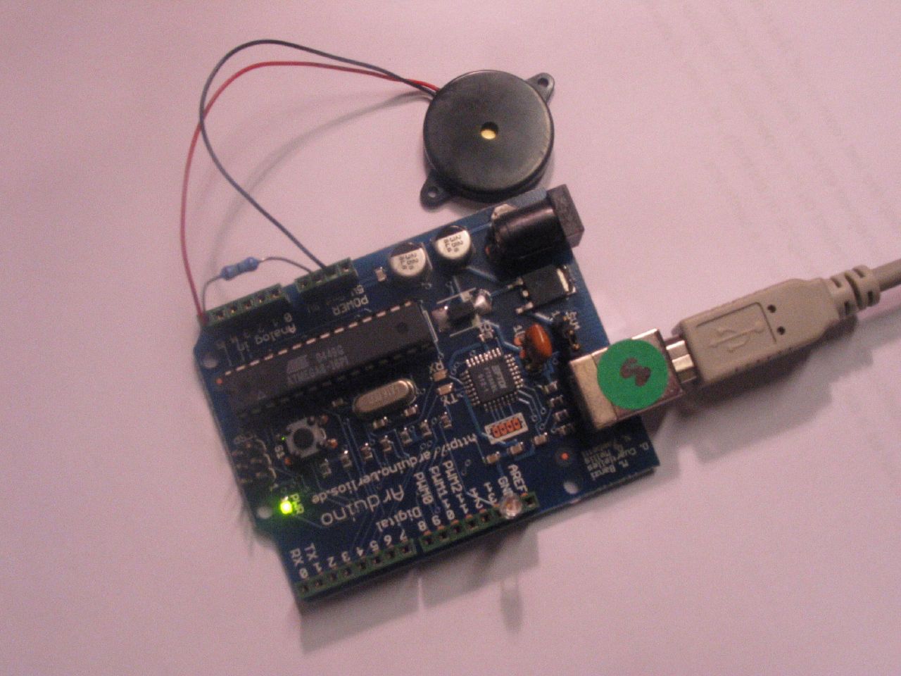
A Piezo is nothing but an electronic device that can both be used to play tones and to detect tones. In our example we are plugging the Piezo on the analog input pin number 0, that supports the functionality of reading a value between 0 and 5volts, and not just a plain HIGH or LOW.
The other thing to remember is that Piezos have polarity, commercial devices are usually having a red and a black wires indicating how to plug it to the board. We connect the black one to ground and the red one to the input. We also have to connect a resistor in the range of the Megaohms in parallel to the Piezo element; in the example we have plugged it directly in the female connectors. Sometimes it is possible to acquire Piezo elements without a plastic housing, then they will just look like a metallic disc and are easier to use as input sensors.
The code example will capture the knock and if it is stronger than a certain threshold, it will send the string "Knock!" back to the computer over the serial port. In order to see this text you can use the Arduino serial monitor.
Example of connection of a Piezo to analog pin 0 with a resistor
/* Knock Sensor
* by DojoDave
*
* Program using a Piezo element as if it was a knock sensor.
*
* We have to basically listen to an analog pin and detect
* if the signal goes over a certain threshold. It writes
* "knock" to the serial port if the Threshold is crossed,
* and toggles the LED on pin 13.
*
* http://www.arduino.cc/en/Tutorial/Knock
*/
int ledPin = 13; // led connected to control pin 13
int knockSensor = 0; // the knock sensor will be plugged at analog pin 0
byte val = 0; // variable to store the value read from the sensor pin
int statePin = LOW; // variable used to store the last LED status, to toggle the light
int THRESHOLD = 100; // threshold value to decide when the detected sound is a knock or not
void setup() {
pinMode(ledPin, OUTPUT); // declare the ledPin as as OUTPUT
Serial.begin(9600); // use the serial port
}
void loop() {
val = analogRead(knockSensor); // read the sensor and store it in the variable "val"
if (val >= THRESHOLD) {
statePin = !statePin; // toggle the status of the ledPin (this trick doesn't use time cycles)
digitalWrite(ledPin, statePin); // turn the led on or off
Serial.println("Knock!"); // send the string "Knock!" back to the computer, followed by newline
delay(10); // short delay to avoid overloading the serial port
}
}
The "Hello World!" of Physical Computing 2
Code 2
Blink Without Delay 3
Code 3
Knight Rider 4
Knight Rider 1 5
Knight Rider 2 6
Knight Rider 3 7
Shooting Star 8
How this works 8
Code 8
PWMAllPins 9
Analog I/O 13
Analog Input 13
Circuit 13
Code 13
Fading 14
Circuit 14
Code 14
Smoothing 14
Circuit 14
Code 14
Knock 15
Digital Output
The "Hello World!" of Physical Computing
The first program every programmer learns consists in writing enough code to make their code show the sentence "Hello World!" on a screen.
As a microcontroller, Arduino doesn't have any pre-established output devices. Willing to provide newcomers with some help while debugging programs, we propose the use of one of the board's pins plugging a LED that we will make blink indicating the right functionallity of the program.
We have added a 1K resistor to pin 13, what allows the immediate connection of a LED between that pin and ground.
LEDs have polarity, which means they will only light up if you orient the legs properly. The long leg is typically positive, and should connect to pin 13. The short leg connects to GND; the bulb of the LED will also typically have a flat edge on this side. If the LED doesn't light up, trying reversing the legs (you won't hurt the LED if you plug it in backwards for a short period of time).
Code
The example code is very simple, credits are to be found in the comments.
/* Blinking LED
* ------------
*
* turns on and off a light emitting diode(LED) connected to a digital
* pin, in intervals of 2 seconds. Ideally we use pin 13 on the Arduino
* board because it has a resistor attached to it, needing only an LED
*
* Created 1 June 2005
* copyleft 2005 DojoDave
* http://arduino.berlios.de
*
* based on an orginal by H. Barragan for the Wiring i/o board
*/
int ledPin = 13; // LED connected to digital pin 13
void setup()
{
pinMode(ledPin, OUTPUT); // sets the digital pin as output
}
void loop()
{
digitalWrite(ledPin, HIGH); // sets the LED on
delay(1000); // waits for a second
digitalWrite(ledPin, LOW); // sets the LED off
delay(1000); // waits for a second
}
Blink Without Delay
Sometimes you need to blink an LED (or some other time sensitive function) at the same time as something else (like watching for a button press). That means you can't use delay(), or you'd stop everything else the program while the LED blinked. Here's some code that demonstrates how to blink the LED without using delay(). It keeps track of the last time it turned the LED on or off. Then, each time through loop() it checks if a sufficient interval has passed - if it has, it turns the LED off if it was on and vice-versa.
Code
int ledPin = 13; // LED connected to digital pin 13
int value = LOW; // previous value of the LED
long previousMillis = 0; // will store last time LED was updated
long interval = 1000; // interval at which to blink (milliseconds)
void setup()
{
pinMode(ledPin, OUTPUT); // sets the digital pin as output
}
void loop()
{
// here is where you'd put code that needs to be running all the time.
// check to see if it's time to blink the LED; that is, is the difference
// between the current time and last time we blinked the LED bigger than
// the interval at which we want to blink the LED.
if (millis() - previousMillis > interval) {
previousMillis = millis(); // remember the last time we blinked the LED
// if the LED is off turn it on and vice-versa.
if (value == LOW)
value = HIGH;
else
value = LOW;
digitalWrite(ledPin, value);
}
}
Knight Rider
We have named this example in memory to a TV-series from the 80's where the famous David Hasselhoff had an AI machine driving his Pontiac. The car had been augmented with plenty of LEDs in all possible sizes performing flashy effects.
Thus we decided that in order to learn more about sequential programming and good programming techniques for the I/O board, it would be interesting to use the Knight Rider as a metaphor.
This example makes use of 6 LEDs connected to the pins 2 - 7 on the board using 220 Ohm resistors. The first code example will make the LEDs blink in a sequence, one by one using only digitalWrite(pinNum,HIGH/LOW) and delay(time). The second example shows how to use a for(;;) construction to perform the very same thing, but in fewer lines. The third and last example concentrates in the visual effect of turning the LEDs on/off in a more softer way.
Example for Hasselhoff's fans
Knight Rider 1
/* Knight Rider 1
* --------------
*
* Basically an extension of Blink_LED.
*
*
* (cleft) 2005 K3, Malmo University
* @author: David Cuartielles
* @hardware: David Cuartielles, Aaron Hallborg
*/
int pin2 = 2;
int pin3 = 3;
int pin4 = 4;
int pin5 = 5;
int pin6 = 6;
int pin7 = 7;
int timer = 100;
void setup(){
pinMode(pin2, OUTPUT);
pinMode(pin3, OUTPUT);
pinMode(pin4, OUTPUT);
pinMode(pin5, OUTPUT);
pinMode(pin6, OUTPUT);
pinMode(pin7, OUTPUT);
}
void loop() {
digitalWrite(pin2, HIGH);
delay(timer);
digitalWrite(pin2, LOW);
delay(timer);
digitalWrite(pin3, HIGH);
delay(timer);
digitalWrite(pin3, LOW);
delay(timer);
digitalWrite(pin4, HIGH);
delay(timer);
digitalWrite(pin4, LOW);
delay(timer);
digitalWrite(pin5, HIGH);
delay(timer);
digitalWrite(pin5, LOW);
delay(timer);
digitalWrite(pin6, HIGH);
delay(timer);
digitalWrite(pin6, LOW);
delay(timer);
digitalWrite(pin7, HIGH);
delay(timer);
digitalWrite(pin7, LOW);
delay(timer);
digitalWrite(pin6, HIGH);
delay(timer);
digitalWrite(pin6, LOW);
delay(timer);
digitalWrite(pin5, HIGH);
delay(timer);
digitalWrite(pin5, LOW);
delay(timer);
digitalWrite(pin4, HIGH);
delay(timer);
digitalWrite(pin4, LOW);
delay(timer);
digitalWrite(pin3, HIGH);
delay(timer);
digitalWrite(pin3, LOW);
delay(timer);
}
Knight Rider 2
/* Knight Rider 2
* --------------
*
* Reducing the amount of code using for(;;).
*
*
* (cleft) 2005 K3, Malmo University
* @author: David Cuartielles
* @hardware: David Cuartielles, Aaron Hallborg
*/
int pinArray[] = {2, 3, 4, 5, 6, 7};
int count = 0;
int timer = 100;
void setup(){
// we make all the declarations at once
for (count=0;count<6;count++) count="0;count<6;count++)" count="5;count">=0;count--) {
digitalWrite(pinArray[count], HIGH);
delay(timer);
digitalWrite(pinArray[count], LOW);
delay(timer);
}
}
Knight Rider 3
/* Knight Rider 3
* --------------
*
* This example concentrates on making the visuals fluid.
*
*
* (cleft) 2005 K3, Malmo University
* @author: David Cuartielles
* @hardware: David Cuartielles, Aaron Hallborg
*/
int pinArray[] = {2, 3, 4, 5, 6, 7};
int count = 0;
int timer = 30;
void setup(){
for (count=0;count<6;count++) count="0;count<5;count++)" count="5;count">0;count--) {
digitalWrite(pinArray[count], HIGH);
delay(timer);
digitalWrite(pinArray[count - 1], HIGH);
delay(timer);
digitalWrite(pinArray[count], LOW);
delay(timer*2);
}
}
Shooting Star
This example shows how to make a ray of light, or more poetically a Shooting Star, go through a line of LEDs. You will be able to controle how fast the 'star' shoots, and how long its 'tail' is. It isn't very elegant because the tail is as bright as the star, and in the end it seems like a solid ray that crosses the LED line.
?v=0
How this works
You connect 11 LEDs to 11 arduino digital pins, through a 220 Ohm resistance (see image above).
The program starts lighting up LEDs until it reaches the number of LEDs equal to the size you have stablished for the tail. Then it will continue lighting LEDs towards the left (if you mount it like and look at it like the image) to make the star keep movint, and will start erasing from the right, to make sure we see the tail (otherwise we would just light up the whole line of leds, this will happen also if the tail size is equal or bigger than 11)
The tail size should be relatively small in comparison with the number of LEDs in order to see it. Of course you can increase the number of LEDs using an LED driver (see tutorial) and therefore, allow longer tails.
Code
/* ShootingStar
* ------------
* This program is kind of a variation of the KnightRider
* It plays in a loop a "Shooting Star" that is displayed
* on a line of 11 LEDs directly connected to Arduino
*
* You can control how fast the star shoots thanx to the
* variable called "waitNextLed"
*
* You can also control the length of the star's "tail"
* through the variable "tail length"
* First it reads two analog pins that are connected
* to a joystick made of two potentiometers
*
* @author: Cristina Hoffmann
* @hardware: Cristina Hofmann
*
*/
// Variable declaration
int pinArray [] = { 2,3,4,5,6,7,8,9,10,11,12 }; // Array where I declare the pins connected to the LEDs
int controlLed = 13;
int waitNextLed = 100; // Time before I light up the next LED
int tailLength = 4; // Number of LEDs that stay lit befor I start turning them off, thus the tail
int lineSize = 11; // Number of LEDs connected (which also is the size of the pinArray)
// I asign the sens of the different Pins
void setup()
{
int i;
pinMode (controlLed, OUTPUT);
for (i=0; i< tailcounter =" tailLength;" i="0;" tailcounter="="> 0)
tailCounter--;
}
for (i=(lineSize-tailLength); i
/*
PWMallPins.pde
Paul Badger 2007
A program to illustrate one way to implement a PWM loop.
This program fades LED's on Arduino digital pins 2 through 13 in a sinewave pattern.
It could be modified to also modulate pins 0 & 1 and the analog pins.
I didn't modulate pins 0 & 1 just because of the hassle of disconnecting the LEDs on the RX and TX pins (0 & 1).
The PWM loop, as written, operates at about 175 HZ and is flicker-free.
The trick to this of course is not doing too much math in between the PWM loop cycles.
Long delays between the loops are going to show up as flicker. This is true especially of "Serial.print" debug statements
which seem to hog the processor during transmission. Shorter (timewise) statements will just dim the maximum brightness of the LED's.
There are a couple of lines of code (commented out) that implement a potentiometer as a speed control for the dimming.
How it works: The PWM loop turns on all LED's whose values are greater than 0 at the start of the PWM loop.
It then turns off the LED's as the loop variable is equal to the channel's PWM modulation value.
Because the values are limited to 255 (just by the table), all LED's are turned off at the end of the PWM loop.
This has the side effect of making any extra math, sensor reading. etc. will increase the "off" period of the LED's duty cycle. Consequently
the brightest LED value (255), which is supposed to represent a "100%" duty cycle (on all the time), dosesn't really do that.
More math, sensor reading etc will increase the "off time", dimming the LED's max brightness. You can (somewhat) make up for this dimming with
smaller series resistors, since LED's can be overrated if they aren't on all of the time.
The up side of this arrangement is that the LED's stay flicker free.
Note that this program could easily be used to modulate motor speeds with the addition of driver transistors or MOSFET's.
*/
long time; // variable for speed debug
float pwmSpeed[14] = {
0, 0, 1.2, 1.3, 1.4, 1.9, .9, .8, .5, 1.2, 1.37, 1.47, .3, 3.2}; // these constants set the rate of dimming
int pwmVal[14]; // PWM values for 12 channels - 0 & 1 included but not used
float pwmFloats[14];
int i, j, k, l, x, y, z, bufsize, pot; // variables for various counters
unsigned char sinewave[] = //256 values
{
0x80,0x83,0x86,0x89,0x8c,0x8f,0x92,0x95,0x98,0x9c,0x9f,0xa2,0xa5,0xa8,0xab,0xae,
0xb0,0xb3,0xb6,0xb9,0xbc,0xbf,0xc1,0xc4,0xc7,0xc9,0xcc,0xce,0xd1,0xd3,0xd5,0xd8,
0xda,0xdc,0xde,0xe0,0xe2,0xe4,0xe6,0xe8,0xea,0xec,0xed,0xef,0xf0,0xf2,0xf3,0xf5,
0xf6,0xf7,0xf8,0xf9,0xfa,0xfb,0xfc,0xfc,0xfd,0xfe,0xfe,0xff,0xff,0xff,0xff,0xff,
0xff,0xff,0xff,0xff,0xff,0xff,0xfe,0xfe,0xfd,0xfc,0xfc,0xfb,0xfa,0xf9,0xf8,0xf7,
0xf6,0xf5,0xf3,0xf2,0xf0,0xef,0xed,0xec,0xea,0xe8,0xe6,0xe4,0xe2,0xe0,0xde,0xdc,
0xda,0xd8,0xd5,0xd3,0xd1,0xce,0xcc,0xc9,0xc7,0xc4,0xc1,0xbf,0xbc,0xb9,0xb6,0xb3,
0xb0,0xae,0xab,0xa8,0xa5,0xa2,0x9f,0x9c,0x98,0x95,0x92,0x8f,0x8c,0x89,0x86,0x83,
0x80,0x7c,0x79,0x76,0x73,0x70,0x6d,0x6a,0x67,0x63,0x60,0x5d,0x5a,0x57,0x54,0x51,
0x4f,0x4c,0x49,0x46,0x43,0x40,0x3e,0x3b,0x38,0x36,0x33,0x31,0x2e,0x2c,0x2a,0x27,
0x25,0x23,0x21,0x1f,0x1d,0x1b,0x19,0x17,0x15,0x13,0x12,0x10,0x0f,0x0d,0x0c,0x0a,
0x09,0x08,0x07,0x06,0x05,0x04,0x03,0x03,0x02,0x01,0x01,0x00,0x00,0x00,0x00,0x00,
0x00,0x00,0x00,0x00,0x00,0x00,0x01,0x01,0x02,0x03,0x03,0x04,0x05,0x06,0x07,0x08,
0x09,0x0a,0x0c,0x0d,0x0f,0x10,0x12,0x13,0x15,0x17,0x19,0x1b,0x1d,0x1f,0x21,0x23,
0x25,0x27,0x2a,0x2c,0x2e,0x31,0x33,0x36,0x38,0x3b,0x3e,0x40,0x43,0x46,0x49,0x4c,
0x4f,0x51,0x54,0x57,0x5a,0x5d,0x60,0x63,0x67,0x6a,0x6d,0x70,0x73,0x76,0x79,0x7c
};
void setup(){
Serial.begin(9600);
DDRD=0xFC; // direction variable for port D - make em all outputs except serial pins 0 & 1
DDRB=0xFF; // direction variable for port B - all outputs
}
void loop(){
// time = millis(); // this was to test the loop speed
// for (z=0; z<1000; pot =" analogRead(0);" y="0;" j =" (j" k =" j">= 256){ // wrop around sinewave table index values that are larger than 256
pwmFloats[k] = pwmFloats[k] - 256;
}
else if (pwmFloats[k] < portd =" 0xFC;" portb =" 0xFF;" z="0;" x="0;" i="2;" x ="="" portd =" PORTD" portb =" PORTB" name="3.Analog I/Ooutline">Analog I/O
Analog Input
A potentiometer is a simple knob that provides a variable resistance, which we can read into the Arduino board as an analog value. In this example, that value controls the rate at which an LED blinks.
We connect three wires to the Arduino board. The first goes to ground from one of the outer pins of the potentiometer. The second goes from 5 volts to the other outer pin of the potentiometer. The third goes from analog input 2 to the middle pin of the potentiometer.
By turning the shaft of the potentiometer, we change the amount of resistence on either side of the wiper which is connected to the center pin of the potentiometer. This changes the relative "closeness" of that pin to 5 volts and ground, giving us a different analog input. When the shaft is turned all the way in one direction, there are 0 volts going to the pin, and we read 0. When the shaft is turned all the way in the other direction, there are 5 volts going to the pin and we read 1023. In between, analogRead() returns a number between 0 and 1023 that is proportional to the amount of voltage being applied to the pin.
Circuit
Code
/*
* AnalogInput
* by DojoDave
*
* Turns on and off a light emitting diode(LED) connected to digital
* pin 13. The amount of time the LED will be on and off depends on
* the value obtained by analogRead(). In the easiest case we connect
* a potentiometer to analog pin 2.
*/
int potPin = 2; // select the input pin for the potentiometer
int ledPin = 13; // select the pin for the LED
int val = 0; // variable to store the value coming from the sensor
void setup() {
pinMode(ledPin, OUTPUT); // declare the ledPin as an OUTPUT
}
void loop() {
val = analogRead(potPin); // read the value from the sensor
digitalWrite(ledPin, HIGH); // turn the ledPin on
delay(val); // stop the program for some time
digitalWrite(ledPin, LOW); // turn the ledPin off
delay(val); // stop the program for some time
}
Fading
Demonstrates the use of analog output (PWM) to fade an LED.
Circuit
An LED connected to digital pin 9.
Code
int value = 0; // variable to keep the actual value
int ledpin = 9; // light connected to digital pin 9
void setup()
{
// nothing for setup
}
void loop()
{
for(value = 0 ; value <= 255; value+=5) // fade in (from min to max) { analogWrite(ledpin, value); // sets the value (range from 0 to 255) delay(30); // waits for 30 milli seconds to see the dimming effect } for(value = 255; value >=0; value-=5) // fade out (from max to min)
{
analogWrite(ledpin, value);
delay(30);
}
}
Smoothing
Reads repeatedly from an analog input, calculating a running average and printing it to the computer. Demonstrates the use of arrays.
Circuit
Potentiometer on analog input pin 0.
Code
// Define the number of samples to keep track of. The higher the number,
// the more the readings will be smoothed, but the slower the output will
// respond to the input. Using a #define rather than a normal variable lets
// use this value to determine the size of the readings array.
#define NUMREADINGS 10
int readings[NUMREADINGS]; // the readings from the analog input
int index = 0; // the index of the current reading
int total = 0; // the running total
int average = 0; // the average
int inputPin = 0;
void setup()
{
Serial.begin(9600); // initialize serial communication with computer
for (int i = 0; i < index =" (index">= NUMREADINGS) // if we're at the end of the array...
index = 0; // ...wrap around to the beginning
average = total / NUMREADINGS; // calculate the average
Serial.println(average); // send it to the computer (as ASCII digits)
}
Knock
Here we use a Piezo element to detect sound, what will allow us to use it as a knock sensor. We are taking advantage of the processors capability to read analog signals through its ADC - analog to digital converter. These converters read a voltage value and transform it into a value encoded digitally. In the case of the Arduino boards, we transform the voltage into a value in the range 0..1024. 0 represents 0volts, while 1024 represents 5volts at the input of one of the six analog pins.
A Piezo is nothing but an electronic device that can both be used to play tones and to detect tones. In our example we are plugging the Piezo on the analog input pin number 0, that supports the functionality of reading a value between 0 and 5volts, and not just a plain HIGH or LOW.
The other thing to remember is that Piezos have polarity, commercial devices are usually having a red and a black wires indicating how to plug it to the board. We connect the black one to ground and the red one to the input. We also have to connect a resistor in the range of the Megaohms in parallel to the Piezo element; in the example we have plugged it directly in the female connectors. Sometimes it is possible to acquire Piezo elements without a plastic housing, then they will just look like a metallic disc and are easier to use as input sensors.
The code example will capture the knock and if it is stronger than a certain threshold, it will send the string "Knock!" back to the computer over the serial port. In order to see this text you can use the Arduino serial monitor.
Example of connection of a Piezo to analog pin 0 with a resistor
/* Knock Sensor
* by DojoDave
*
* Program using a Piezo element as if it was a knock sensor.
*
* We have to basically listen to an analog pin and detect
* if the signal goes over a certain threshold. It writes
* "knock" to the serial port if the Threshold is crossed,
* and toggles the LED on pin 13.
*
* http://www.arduino.cc/en/Tutorial/Knock
*/
int ledPin = 13; // led connected to control pin 13
int knockSensor = 0; // the knock sensor will be plugged at analog pin 0
byte val = 0; // variable to store the value read from the sensor pin
int statePin = LOW; // variable used to store the last LED status, to toggle the light
int THRESHOLD = 100; // threshold value to decide when the detected sound is a knock or not
void setup() {
pinMode(ledPin, OUTPUT); // declare the ledPin as as OUTPUT
Serial.begin(9600); // use the serial port
}
void loop() {
val = analogRead(knockSensor); // read the sensor and store it in the variable "val"
if (val >= THRESHOLD) {
statePin = !statePin; // toggle the status of the ledPin (this trick doesn't use time cycles)
digitalWrite(ledPin, statePin); // turn the led on or off
Serial.println("Knock!"); // send the string "Knock!" back to the computer, followed by newline
delay(10); // short delay to avoid overloading the serial port
}
}

Assinar:
Postagens (Atom)